15. The firewall test zone
In this chapter
You will learn
- why the platform needs its own zone behind the Enterprise firewall, and what the L3-ENTFW class measures through it
- the two ways to connect the zone - option B, the plan's default (the free transfer VSI 4003 on the existing firewall bundle, reached through the Border Leaf attachment points), and option A, the alternative (direct 10G links from the TX switches, S-VLAN 3300) - with their configuration, advantages and drawbacks
- how a failure in the test path can affect the firewall cluster in each option, and what the firewall team has to confirm
- how VPN-CORE reaches the zone today (default route) and how the zone should be advertised (OSPF 1 or static routes), including the verification commands
- which objects, services, rules and settings the Enterprise firewall and the DC firewall need, and why every rule exists in both directions
- how a cluster failover appears in the measurements, how the gateway-MAC tracker restores the affected streams, and what decides how fast that happens
Prerequisites: Chapter 12, Chapter 13, Chapter 14
The customer asked for measurements "L3 between VRFs" and "through the firewall". At LVR both mean the same device: the Enterprise firewall cluster CPF-ZV01/ZV02 (ENT-FW), the hub between VPN-CORE, VPN-WAN and VPN-WLAN. To measure through it, TRex needs a destination behind it. Putting TRex clients into existing production zones would mix test traffic with production subnets, IPAM and rule bases. The plan therefore creates a small, dedicated TRex zone on the firewall. This chapter explains that zone, the two ways to connect it - option B, which the plan recommends and uses as its default, and option A, the alternative - and everything the firewall team and the switch team must do for it.
What the zone is and what it measures
The Enterprise firewall as found
Both Border Leafs connect their local cluster member with Bridge-Aggregation10, an LACP bundle of two 10G ports - one per IRF member (Ten-GigabitEthernet1/3/5 and 2/3/5, description "CPF-ZV01 - inside" on sw-rzk-BL and "CPF-ZV02 - inside" on sw-rzc-BL). The bundle is a trunk for VLANs 4000-4003, each mapped to a VSI:
| VLAN / VSI | Description in the config | Gateway on the BLs | Use |
|---|---|---|---|
| 4000 | Transfer VPN-WLAN | Vsi-interface20 | VPN-WLAN to firewall |
| 4001 | Transfer VPN-WAN ENT-FW | Vsi-interface30 | VPN-WAN to firewall |
| 4002 | Transfer VPN-CORE ENT-FW | Vsi-interface40, 10.9.0.17/29 (sw-rzk-BL), 10.9.0.18/29 (sw-rzc-BL) | VPN-CORE to firewall, OSPF 1 |
| 4003 | Transfer ENTFW *frei* | none | free - no MAC addresses learned in February 2025; the TRex zone with option B |
Several observations show that CPF-ZV01 and CPF-ZV02 form one stretched ClusterXL: both Border Leafs see a single
OSPF neighbour 10.9.0.22 on Vsi40, each member's MAC address is local on "its" Border Leaf, and the sync VLAN 123
"Sync_FW-innen" is a stretched VSI confirm with the firewall team. The ARP view of the
transfer network shows the members and the cluster address. verified Real output, diag
file diag_sw-rzk-BL_20250217-163816.txt, command display evpn route arp (EVPN CR PDF p. 20), VPN-CORE part:
VPN instance: VPN-CORE                        Interface: Vsi-interface40
IP address      MAC address     Router MAC      VSI index   Flags
10.9.0.17       ec9b-8b67-37b8  ec9b-8b67-37b8  513         GL
10.9.0.18       ec9b-8b67-3434  ec9b-8b67-3434  513         BGI
10.9.0.19       ec9b-8b64-af88  ec9b-8b64-af88  513         BGI
10.9.0.20       001c-7f65-8ec8  ec9b-8b67-37b8  513         DL
10.9.0.21       001c-7f65-ff14  ec9b-8b67-3434  513         B
10.9.0.22       001c-7f65-ff14  ec9b-8b67-3434  513         B
How to read it: flags G = gateway, L = local, D = dynamic, B = learned through BGP. 10.9.0.17/.18/.19 are the
three Border Leafs. 10.9.0.20 is local on sw-rzk-BL (the member in RZK, CPF-ZV01), 10.9.0.21 was learned from sw-rzc-BL
(CPF-ZV02). The cluster address 10.9.0.22 resolves to the same MAC as 10.9.0.21: on 17 February 2025, traffic to the
cluster was delivered to the member in Chorweiler. The same command on sw-rzc-BL shows 10.9.0.21 and 10.9.0.22 as local
(DL). Keep this in mind - it decides how many DCI crossings the firewall classes contain
(Chapter 14).
The proposed zone
| Item | Proposal | Status |
|---|---|---|
| Zone VLAN on the firewall | 4003 with option B (the existing, free transfer VSI VPN-4003); 1420 (unused in all nine configs) only with option A | decision, option B recommended |
| Subnet | 10.9.90.0/24 (unused) | decision, IPAM approval |
| Cluster address (VIP) | 10.9.90.1 | decision |
| Member addresses | 10.9.90.2 (CPF-ZV01), 10.9.90.3 (CPF-ZV02) | decision |
| TRex monitoring pool | 10.9.90.101-116; zone clients 10.9.90.106 (at K-BL, MAC 02:54:52:06:0f:a3) and 10.9.90.113 (at C-BL, 02:54:52:0d:0f:a3); option A instead: 10.9.90.114 (AP FW, 02:54:52:0e:05:8c) | decision |
| TRex lab pool | 10.9.90.151-166; lab zone client 10.9.90.156 on p6 (fixed port MAC 02:54:52:f0:00:06); option A instead: 10.9.90.164 (same MAC - it belongs to the port, not to the AP) | decision |
Both options use the same subnet, the same address formula, the same firewall objects and rules and the same trexctl
group l3-entfw; only the inventory entry of the zone and the switch configuration differ.
The measured path
The L3-ENTFW class sends from VLAN 1314 clients (VPN-CORE) to a zone client and back. Forward, the packet is routed twice: on sw-rzk-BL from Vsi-interface914 to Vsi-interface40 (the transfer network 10.9.0.16/29), and on the firewall from its VPN-CORE side into the zone. The animation shows option B: the zone interface is a VLAN 4003 sub-interface on the same bond, so the frame comes back on Bridge-Aggregation10 tagged 4003, sw-rzk-BL only bridges it in VSI VPN-4003, and TRex receives it through the K-BL attachment point. Its last step shows what option A would change. Chapter 14 walks through every hop.
Notice where the firewall sits in the animation: between the transfer network and the zone. Everything this chapter decides - which physical path the zone uses, which routes and rules exist - concerns the firewall and what lies behind it; the VPN-CORE part of the path is the same as for L3-BL.
Option B - the free transfer VSI 4003 (the plan's default)
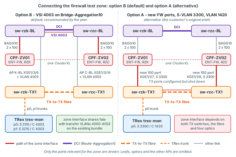
The firewall zone is the existing, free transfer VSI 4003: the firewall team adds a VLAN 4003 interface (VIP 10.9.90.1) on the bond that already connects both cluster members to the Border Leafs, and TRex reaches the zone through the Border Leaf attachment points K-BL and C-BL like any other VLAN. The plan recommends this option and uses it as the default in its inventory, profiles and test procedures; so does this course.
What already exists
The configuration already contains the unused transfer network: VLAN/VSI 4003 "Transfer ENTFW *frei*", trunked on Bridge-Aggregation10 of both Border Leafs. verified Existing configuration, identical on sw-rzk-BL and sw-rzc-BL (running configurations of 17 Feb 2025), shortened to VLAN 4003:
interface Bridge-Aggregation10
 description --> Channel to ENT-FW ZV01 inside
 port link-type trunk
 undo port trunk permit vlan 1
 port trunk permit vlan 4000 to 4003
 link-aggregation mode dynamic
 #
 service-instance 4003
  encapsulation s-vid 4003
  xconnect vsi VPN-4003
#
vsi VPN-4003
 description Transfer ENTFW *frei*
 statistics enable
 vxlan 4003
 evpn encapsulation vxlan
  route-distinguisher auto
  vpn-target 1:4003 export-extcommunity
  vpn-target 1:4003 import-extcommunity
| Line | What it does | Why it matters for option B |
|---|---|---|
port trunk permit vlan 4000 to 4003 |
VLAN 4003 is already allowed on the bundle to the firewall member | No change on Bridge-Aggregation10 is needed |
service-instance 4003 / xconnect vsi VPN-4003 |
Maps tagged 4003 frames from the firewall into the VSI | The firewall's new VLAN 4003 interface is reachable at once |
vsi VPN-4003 / vxlan 4003 / evpn encapsulation vxlan |
VSI with VNI 4003, MACs distributed by EVPN | The VSI is stretched between the Border Leafs; no gateway is configured |
statistics enable |
Packet statistics for the VSI | As on the other transfer VSIs |
The IMET table of sw-rzk-BL lists exactly one remote VTEP for VSI VPN-4003 - sw-rzc-BL (172.31.1.254, tunnel mode VXLAN-DCI). The VSI therefore exists only on the two Border Leafs and is stretched between them; no Leaf and not RZD take part.
What option B adds
- Firewall team: a VLAN 4003 sub-interface on the existing inside bond of both members, cluster address 10.9.90.1/24, member addresses .2/.3.
- Switch team: VLAN 4003 with its service instance on both Border Leaf attachment points - K-BL (sw-rzk-BL XGE1/3/6) and C-BL (sw-rzc-BL XGE1/3/14), Chapter 13. The TX switches need no change for the zone: there is no firewall AP in the inventory; the option-A ports XGE1/1/7 (sw-rzk-TX1) and XGE1/1/8 (sw-rzc-TX1) are configured (PVID 3300, QinQ) but shut down, and S-VLAN 3300 exists and is permitted on the trunks without an active member port (Chapter 12).
- TRex: one zone client per data centre, addressed with the deterministic formula (VLAN 4003 = 0x0FA3): at K-BL
(index 6) in the namespace {p0, S 3110, C 4003}: 10.9.90.106 / 02:54:52:06:0f:a3; at C-BL (index 13) in
{p1, S 3210, C 4003}: 10.9.90.113 / 02:54:52:0d:0f:a3. Both use the VIP 10.9.90.1 as their default gateway. The group
l3-entfwsends from K-L11 and K-BL to the zone client at K-BL and from C-L21 and C-BL to the zone client at C-BL: the zone client sits at the BL AP of the same data centre. The lab port p6 is pinned toFWZ, the inventory alias for K-BL with VLAN 4003 (PVID 3110); its lab zone client is 10.9.90.156 (lab pool .151 + index 6 - 1) with p6's fixed port MAC 02:54:52:f0:00:06.
confirm on device Addition on the two Border Leaf AP ports. The style is identical to
the existing service instances on Bridge-Aggregation10 (LVR running configuration); port trunk permit vlan: L2CR PDF
p. 205. Chapter 13 shows the complete AP port configuration.
| Line | What it does | Why |
|---|---|---|
port trunk permit vlan 1314 to 1315 4003 |
Permits the two test VLANs and the zone VLAN on the AP trunk | TRex sends the zone client's frames with C-tag 4003 |
service-instance 4003 / encapsulation s-vid 4003 |
Matches frames tagged 4003 on this port | Same access model as every server port |
xconnect vsi VPN-4003 |
Maps them into the existing VSI | The zone clients become hosts in the firewall's VLAN 4003 |
Advantages. No new firewall ports, no new cabling, no new optics. The zone interface uses the existing bundle with its LACP redundancy and fails only when the bundle, the Border Leaf or the DCI fails - exactly like the three production transfer interfaces 4000-4002 on the same bundle. The TX switches and the TX-to-TX fibre are not part of any firewall interface, so a failure of the measurement infrastructure cannot affect the cluster.
Drawbacks. It does not provide the physical firewall link from the TX switch that the customer originally asked
for. The zone leg crosses the fabric: the firewall returns the packet over its bundle to a Border Leaf, which bridges it
in VSI 4003 to the BL attachment point - a few tens of microseconds, identical for all zone streams. When the active
member is in the other data centre than the zone client, the zone leg also crosses the DCI, so it contains more than the
firewall. The K-BL and C-BL attachment points now also carry VLAN 4003, and the pairs [K-BL, K-BL] and [C-BL, C-BL]
enter and leave the fabric through the same AP link. LVR must confirm that VSI 4003 is really free and may be dedicated
to the TRex zone.
Option A - direct links from the TX switches (the alternative)
Option A is the customer's original wish: each cluster member gets a new physical 10G interface that is connected directly to a TX switch. The TX-switch side is already prepared: the two zone ports are configured but shut down, and S-VLAN 3300 is defined and permitted on the trunks of both TX switches. Everything else in this section happens only if option A is chosen instead of the default:
- CPF-ZV01 to sw-rzk-TX1 XGE1/1/7, CPF-ZV02 to sw-rzc-TX1 XGE1/1/8: cabling, one SR optic per TX switch and
undo shutdown(with option B both ports stay shut down); - both TX-switch ports are QinQ access ports in S-VLAN 3300; S-VLAN 3300 is also permitted on the TX-to-TX trunk and on the TRex monitoring trunks, so both members and the TRex zone client share one Layer 2 domain;
- on the firewall a VLAN 1420 interface on the new port (for example eth1-05.1420), cluster address 10.9.90.1, member addresses .2/.3;
- in TRex the zone becomes an attachment point of its own,
FW(index 14): zone client {p0, S 3300, C 1420} 10.9.90.114 / 02:54:52:0e:05:8c, lab zone client 10.9.90.164 (lab pool .151 + index 14 - 1) with p6's fixed port MAC 02:54:52:f0:00:06, p6 re-pinned to PVID 3300. The groupsl3-entfwanddscp-entfwthen usedst_vlan: 1420andFWas the second AP of every pair.
If the members turned out to be independent clusters rather than one stretched cluster, option A would need two local S-VLANs (3300 in RZK, 3310 in RZC) and two subnets.
confirm on device The option-A port as it is pre-provisioned on sw-rzk-TX1; sw-rzc-TX1
has the same VLAN and port Ten-GigabitEthernet1/1/8 towards CPF-ZV02. The commands are verified for the 5950 R630x
(port link-type, port access vlan, port trunk permit vlan: L2CR PDF pp. 202-205; qinq enable: L2CG PDF p. 222,
L2CR PDF p. 278); the port numbers assume the planned module layout of the TX switches.
vlan 3300
 name TRX-AP-FW-ZONE-stretched
#
interface Ten-GigabitEthernet1/1/7
 description TRX AP FW-ZONE (option A) --> CPF-ZV01 <FW-PORT>
 port link-type access
 port access vlan 3300
 qinq enable
 shutdown
| Line | What it does | Why |
|---|---|---|
vlan 3300 |
Creates the S-VLAN of the firewall AP | One S-VLAN for the whole zone, on both TX switches; harmless with option B because no active port is a member |
port link-type access / port access vlan 3300 |
The member port is an untagged member of S-VLAN 3300 | The S-tag is pushed on ingress and removed on egress |
qinq enable |
Pushes the PVID 3300 onto every incoming frame, tagged or not | The firewall's VLAN 1420 tag stays intact as the inner tag |
shutdown |
Keeps the port down with option B | Enabling option A is cabling plus undo shutdown - no other TX-switch change |
(trunks) port trunk permit vlan ... 3300 |
Already in the permit lists of the TX-to-TX trunk (HGE1/2/1) of both switches and of the TRex trunks XGE1/1/21-24 |
The member in RZC and TRex must be in the same domain (Chapter 12) |
Why may S-VLAN 3300 contain two AP ports?
Every other S-VLAN contains exactly one AP port, so that a production VLAN can never be bridged between two APs outside the fabric. With option A, S-VLAN 3300 deliberately contains two - the zone ports of CPF-ZV01 and CPF-ZV02 - because both members of a cluster must share one Layer 2 domain for the cluster address. This is safe: VLAN 1420 exists in no fabric VSI, and a firewall routes between its interfaces instead of bridging, so no loop through the fabric can form.
Advantages. Option A matches the customer's original requirement of physical links from the TX switches to the firewall. The zone leg of the path is short and independent of the fabric - from the firewall straight to the TX switch, no Leaf and no Border Leaf in between - so the measurement isolates the firewall better. Production bundles stay untouched.
Drawbacks. It needs a free 10G port on each member, two Check Point certified SFP+ SR optics on the firewall side, one more SR optic per TX switch and cabling to the TX switches. The zone traffic of CPF-ZV02 crosses the TX-to-TX fibre. Above all, the new interface becomes part of the cluster: the TX switches, the TX-to-TX fibre and four optics turn into components of a firewall interface - see the failure analysis below.
The decision
Open decision: how the firewall test zone is connected
Option B - existing VSI 4003 on Bridge-Aggregation10 (recommended by the plan, used as the default). Needs no hardware and adds no new failure mode to the cluster, because the zone interface shares the fate of the existing transfer interfaces. The zone leg crosses the fabric, VSI 4003 is used up, and the firewall is not reached over a physical link from the TX switch.
Option A - direct links (S-VLAN 3300, VLAN 1420; the alternative). Fulfils the customer's original requirement of a physical firewall link from the TX switches and keeps the zone leg free of fabric hops. Requires new ports and optics on both members and a confirmed, supported way to keep a failure of the test path from affecting the cluster - or a formal risk acceptance.
The plan recommends option B and uses it as the default; option A - a new firewall port per member on the TX switches, the customer's original wish - remains the alternative decision. The LVR network and firewall teams still have to confirm the choice. What decides it: whether the physical link is worth a new dependency of the cluster. Option A needs a supported answer of the firewall team to the question "can the zone interface be made non-critical for failover on our Check Point version?" - without one, it means accepting that a TX switch reboot or a fibre cut may trigger a production failover.
| Criterion | Option B (default) | Option A (alternative) |
|---|---|---|
| New firewall hardware | none | one 10G port per member, optics, cabling |
| Matches "physical FW link from the TX switch" | no | yes |
| Zone leg crosses the fabric | yes (Border Leaf; also the DCI when the active member is not in the zone client's DC) | no |
| TX switches/fibre part of a firewall interface | no | yes |
| New failure mode for the cluster | no | yes, unless solved by the FW team |
| Changes on the switches | VLAN 4003 and service instance 4003 on the K-BL and C-BL APs | TX switches: undo shutdown on the two pre-configured zone ports (S-VLAN 3300 and the trunk permits already exist) |
| Firewall VLAN / interface | VLAN 4003 on the existing bond | VLAN 1420 on the new port |
| TRex zone clients | {p0, S 3110, C 4003} 10.9.90.106 and {p1, S 3210, C 4003} 10.9.90.113 | {p0, S 3300, C 1420} 10.9.90.114 |
| Lab zone client (p6, fixed MAC 02:54:52:f0:00:06) | 10.9.90.156, PVID 3110 | 10.9.90.164, PVID 3300 |
ClusterXL failure-mode analysis
What is known at the level relevant for this design: ClusterXL monitors the interfaces of the cluster. A failure of a monitored interface can put a member into a problem state. If that member is the active one, the cluster fails over - a production event for every VRF that crosses the firewall. If it is the standby member, the cluster loses its redundancy until the interface recovers. Which interfaces are monitored, and whether and how an interface can be excluded from this decision, depends on the Check Point version and configuration; the firewall team must confirm the supported mechanism or formally accept the risk. This risk is the reason why the plan recommends option B: there, no cluster interface depends on the measurement infrastructure.
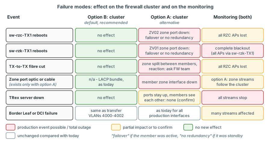
| Event | Option B (default) - effect on the cluster | Option A (alternative) - effect on the cluster | Effect on the monitoring |
|---|---|---|---|
| sw-rzc-TX1 reboots | None - the TX switches are not part of any firewall interface | The zone port of CPF-ZV02 goes down: failover if ZV02 is the active member (as in February 2025), loss of redundancy if it is the standby | All RZC APs lost for the duration, with option B including the zone client at C-BL; option A: zone reachable only via ZV01 |
| sw-rzk-TX1 reboots | None | The zone port of CPF-ZV01 goes down (failover or loss of redundancy); the zone port of ZV02 stays up but no longer reaches its peer or TRex | Complete blackout: every AP reaches TRex through sw-rzk-TX1 |
| TX-to-TX fibre cut (option A also: S-VLAN 3300 removed from the trunk) | None | Both zone ports stay up, but the zone is split: the members cannot see each other on this interface; the reaction is version- and configuration-dependent | All RZC APs lost; option B: the zone client at K-BL keeps working; option A: zone reachable only on the ZV01 side |
| Optic or cable of a zone port (option A only) | Not applicable (no new port; a bundle member failure is handled by LACP as today) | That member's zone interface goes down - as above | Option A: zone streams follow the cluster's reaction |
| TRex server or monitoring ports down | None | Zone ports stay up and the members still see each other through S-VLAN 3300 - no cluster impact expected confirm | All streams stop |
| Border Leaf reboot or DCI failure | Zone interface behaves exactly like transfer VLANs 4000-4002 | Unchanged compared with today (affects the production interfaces anyway) | Many streams affected |
Production impact
The statement "a failure of the TX switches never affects production" is true for every attachment point of a Leaf or Border Leaf and, with option B, the default, for the firewall as well. If option A were chosen, it would hold for the firewall only once the firewall team has solved the interface monitoring question. Until then, treat a TX-switch reboot, a TX-switch software upgrade and any work on the TX-to-TX fibre as a potential firewall failover - with change control and the firewall team informed.
Routing the zone in VPN-CORE
Today: the default route already points to the firewall
VPN-CORE has a default route learned by OSPF from the firewall. Any new prefix behind the firewall - including
10.9.90.0/24 - is therefore reachable from VPN-CORE without any switch change. verified
Real output, selected lines, diag file diag_sw-rzk-BL_20250217-163816.txt, command
display ip routing-table all-vpn-instance:
VPN instance: VPN-CORE
Destinations : 1526 Routes : 1526

Destination/Mask   Proto   Pre Cost        NextHop         Interface
0.0.0.0/0          O_ASE1  150 2           10.9.0.22       Vsi40
...
10.3.0.0/16        Static  60  0           10.9.0.35       Vsi44
...
10.3.14.0/24       Direct  0   0           10.3.14.1       Vsi914
...
10.3.15.0/24       Direct  0   0           10.3.15.1       Vsi915
...
10.9.0.16/29       Direct  0   0           10.9.0.17       Vsi40
The 10.3.0.0/16 static route to the DC firewall (10.9.0.35) does not interfere: the connected /24 networks of the test
VLANs are more specific. The return path is in place as well: OSPF 1 on both Border Leafs redistributes connected
networks (import-route direct), and only sw-rzk-BL owns 10.3.14.0/24 and 10.3.15.0/24 - so the firewall should reach
the TRex clients via 10.9.0.17 (the firewall team can confirm this in its routing table).
Recommended: the firewall advertises the zone into OSPF 1
Relying on the default route works, but an explicit route is cleaner: it is visible in every routing table, it documents
the zone, and it keeps working if the default route is ever moved to another next hop. The firewall is already an OSPF 1
neighbour of all three Border Leafs on Vsi40 (area 0.0.0.0, MD5 authentication configured on the BLs).
verified Real output, diag file diag_sw-rzk-BL_20250217-163816.txt, command
display ospf peer, process 1:
     OSPF Process 1 with Router ID 10.9.0.17
               Neighbor Brief Information

 Area: 0.0.0.0
 Router ID       Address         Pri Dead-Time  State             Interface
 10.9.0.18       10.9.0.18       1   38         Full/DROther      Vsi40
 10.9.0.19       10.9.0.19       1   40         Full/DROther      Vsi40
 10.9.0.22       10.9.0.22       1   38         Full/BDR          Vsi40
The firewall team announces 10.9.90.0/24 into this OSPF process; how (redistribution of the connected network or a passive OSPF interface) is their choice. On the Border Leafs the route then appears with next hop 10.9.0.22.
Alternative: static routes on both Border Leafs
verified Syntax identical to the existing VPN-CORE static routes on both Border Leafs and
to Layer 3 - IP Routing Command Reference R630x, PDF pp. 89-90 (ip route-static vpn-instance):
| Part | Meaning |
|---|---|
vpn-instance VPN-CORE |
The route is installed in VPN-CORE |
10.9.90.0 24 |
The zone subnet |
10.9.0.22 |
Next hop: the firewall's cluster address on the transfer network Vsi40 |
description TRex-FW-zone |
Optional; the existing statics use descriptions such as "zur DC-FW" |
Because import-route static is configured in ospf 1 on both Border Leafs, the static route is redistributed and the
third Border Leaf (sw-rzd-BL) learns the zone as well. On sw-rzc-BL all existing VPN-CORE static routes carry
preference 70; the switch team decides whether the new route follows that local convention. Removal:
undo ip route-static vpn-instance VPN-CORE 10.9.90.0 24 10.9.0.22. Use either OSPF or static routes, not both.
Verification
| Where | Command | What you expect |
|---|---|---|
| Both BLs | display ip routing-table vpn-instance VPN-CORE 10.9.90.0 24 |
10.9.90.0/24 via 10.9.0.22 (OSPF or Static) and 0.0.0.0/0 via 10.9.0.22 - the command lists every active route with a mask of at most /24 that covers the address; add longer-match to see only the most specific one (L3 IP Routing CR PDF pp. 25-26) |
| Both BLs | display ospf peer |
10.9.0.22 in state Full on Vsi40 (L3 IP Routing CR PDF p. 181) |
| sw-rzk-BL | display evpn route arp vpn-instance VPN-CORE |
Which MAC answers for 10.9.0.22, and whether it is local (DL) or behind the other BL (B) |
| sw-rzk-BL | display arp vpn-instance VPN-CORE |
The VLAN-1314 TRex clients 10.3.14.1xx resolved (L3 IP Services CR PDF p. 33) |
| Both BLs (option B) | display l2vpn mac-address vsi VPN-4003 |
The zone client MACs - 0254-5206-0fa3 local on sw-rzk-BL, 0254-520d-0fa3 local on sw-rzc-BL - and firewall MACs on Bridge-Aggregation10 (VXCR PDF p. 13) |
| TRex | EMU zone clients 10.9.90.106 and 10.9.90.113 | Gateway 10.9.90.1 resolved (dgw.resolve true, dgw.rmac = the MAC answering for the VIP, TREX-EMU "EMU Client") |
If only the default route appears, the zone is still reachable - but it has not been advertised yet.
Firewall objects, services and rules
Enterprise firewall
The firewall configuration is done by the LVR firewall team; the names below are proposals. They are the same for both options of the zone.
| Item | Content |
|---|---|
| Address range TRX-mon-1314 | 10.3.14.101-10.3.14.116 (monitoring clients in VLAN 1314) |
| Address range TRX-lab-1314 | 10.3.14.151-10.3.14.166 (lab clients in VLAN 1314) |
| Address range TRX-mon-1315 | 10.3.15.101-10.3.15.116 |
| Address range TRX-mon-<VLAN> | the 16-address pool of each further VLAN under test |
| Address range TRX-fwzone | 10.9.90.101-10.9.90.116 (monitoring zone clients, by default .106 and .113) |
| Address range TRX-fwzone-lab | 10.9.90.151-10.9.90.166 (lab zone client, by default .156) |
| Groups | TRX-inside (the inside ranges TRX-mon-* and TRX-lab-1314), TRX-zone (TRX-fwzone and TRX-fwzone-lab) |
| Service TRX-udp | UDP 32000-32099 (destination) |
| Service ICMP | echo request / reply |
| Service TRX-tcp | TCP 80, 443, 8080 (ASTF lab tests only) |
| # | Source | Destination | Service | Action |
|---|---|---|---|---|
| 1 | TRX-inside | TRX-zone | TRX-udp, ICMP | Accept, log |
| 2 | TRX-zone | TRX-inside | TRX-udp, ICMP | Accept, log |
| 3 | TRX-astf-clients: 10.9.92.0/24 or the lab client 10.3.14.151 | TRX-astf-servers: 10.9.93.0/24 or the lab zone client 10.9.90.156 (option A: .164) | TRX-tcp | Accept - only for stateful lab tests |
The rules must sit above any cleanup or drop rule. No NAT for any TRex object: if an automatic hide NAT exists for the inside networks, an explicit "no NAT" rule is needed. TRex sends to the real client addresses and expects to receive from them; a translated address would also break the reverse stream.
Why does every rule exist in both directions?
A firewall rule for UDP normally covers a flow and its replies. TRex streams are not replies to each other. The forward stream K-L11 to the zone uses 10.3.14.101:40000+n to 10.9.90.106:32004; the reverse stream uses 10.9.90.106:40000+m to 10.3.14.101:32004. A reply to the forward stream would have to come from port 32004 and go to port 40000+n - the reverse stream does neither. Each direction is its own session, opened from its own side, and therefore needs its own rule.
Three more items for the firewall team:
- IPv4 identification and TOS. TRex rewrites the IPv4 identification field of every flow-statistics and latency packet and recognises its packets by it: a flow-stat stream carries a reserved base (0xFC00 in the v3.x source; the TREX-STL guide names the range 0xff00-0xffff) plus an internal hardware ID, a latency stream the value 0xFFFF. A function that rewrites the IPv4 ID would make the packets unrecognisable for TRex. TRex also sets bit 0 of the TOS byte on these packets (EF 0xB8 leaves as 0xB9; DSCP unchanged, ECN field 01). The DSCP carries the marking of the DSCP class; re-marking it is exactly what that class is meant to detect. Ask the team whether any such normalisation (IP ID, TOS, ECN) applies to these rules.
- UDP checksum 0. Latency streams are sent with UDP checksum 0 ("no checksum", legal for IPv4), because TRex writes the signature into every packet without recalculating the checksum. A firewall that verifies UDP checksums must accept them confirm on the bench.
- Topology and anti-spoofing. The zone interface must accept 10.9.90.0/24 as its own network (topology internal, "network defined by the interface IP and net mask"), and the interface on the VPN-CORE side must accept the TRex pools as sources, otherwise packets are dropped as spoofed.
Open decision: inspection of TRex traffic
Exclude TRex traffic from Threat Prevention / IPS (plan default): the monitoring measures pure forwarding, latency stays stable, and the firewall's inspection engines are not loaded by synthetic traffic. Include it: the measurement shows what production flows experience, including inspection latency - but changes of inspection profiles then appear as latency changes. A middle way is a separate inspection profile used only for lab tests. The firewall team decides together with LVR operations.
Sessions and timeouts
Each stream has a fixed 5-tuple, so each stream is exactly one firewall session: 8 L3-ENTFW streams plus 8 DSCP streams through the ENT-FW (BE, EF, AF41 and CS1 in both directions) make 16 sessions in the default profile, the 8 L3-DCFW streams 8 sessions on the DC-FW. The default UDP virtual session timeout on Check Point is 40 seconds. A stream at 50 pps sends a packet every 20 ms, so the session never idles out while the stream runs. When trex-mon is stopped for longer than 40 s, the sessions expire and are created again with the first packet after the restart; a restart within 40 s simply continues the existing sessions. The rate limit of 100 pps per stream through a firewall keeps the load on a shared production device negligible (Chapter 16).
DC firewall (class L3-DCFW)
The DC firewall CPF-ZV05/06 already is the gateway of the production VLANs used by L3-DCFW, so it needs no interface change - only rules between the TRex pools of VLAN A and VLAN B: TRX-mon-<A> to TRX-mon-<B> and back, services TRX-udp and ICMP, accept, no NAT. The pools must be reserved in IPAM and excluded from any DHCP scope of these VLANs. The inspection decision above applies to these rules as well.
How a cluster failover appears in the measurements
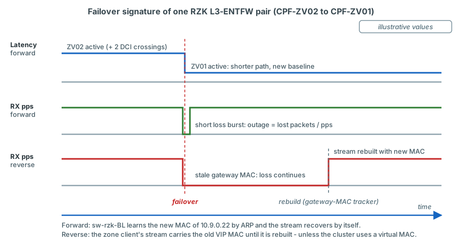
A failover of the Enterprise firewall leaves three traces in the TRex data:
- A latency step on the firewall streams at the same moment. With the gateway in Kalk and the zone on VSI 4003 (option B), a move of the active member from CPF-ZV02 to CPF-ZV01 removes two DCI crossings from every RZK L3-ENTFW stream - the way to the firewall and the zone leg back through VSI 4003 both become local to sw-rzk-BL - and the move back adds them. The RZC L3-ENTFW streams cross the DCI twice with either member; only the leg of the second crossing changes (Chapter 14). L2 and L3-BL streams do not change. With option A the same move would remove one DCI and one TX-fibre crossing from every L3-ENTFW stream.
- A short loss burst while the cluster switches over. The outage duration is lost packets / pps; at 50 pps the resolution is 20 ms.
- Possibly persistent loss in some directions. TRex writes the destination MAC of a routed stream into the stream's
packet once, when the stream is built. In February 2025 the cluster address 10.9.0.22 resolved to the MAC of a member
(
001c-7f65-ff14, the MAC of 10.9.0.21), and the DC-FW address 10.9.0.35 likewise to an RZC member MAC: the active members were in RZC and no virtual MAC was seen. If the cluster answers its addresses with the active member's own MAC, then after a failover the Border Leafs learn the new MAC by ARP, but the TRex streams whose first hop is the cluster - the reverse L3-ENTFW streams and the reverse DSCP copies (zone client to VIP 10.9.90.1) and, on a DC-FW failover, both directions of L3-DCFW - keep sending to the old MAC until they are rebuilt. A ClusterXL virtual MAC avoids the issue; whether the cluster uses one must be confirmed by the firewall team.
How the streams recover: the gateway-MAC tracker
trexctl's gateway-MAC tracker polls dgw.rmac every 10 s and rebuilds the affected streams (event
gateway_mac_changed). How fast EMU learns the new MAC depends on how ClusterXL announces it: a gratuitous ARP request
is learned at once, a broadcast ARP reply is ignored and the next periodic query (every 60 s by default) is needed. The
plan's target of 15 s therefore needs a shorter ARP timer for the firewall VLANs or a forced query
confirm on device.
In more detail (Chapter 18 shows the implementation):
- What is watched. Every VLAN whose gateway is a firewall cluster carries
gateway_mac_tracking: truein the inventory - with option B the zone VLAN 4003 (option A: 1420) and the production VLANs of L3-DCFW;trexctl inventory validateenforces it. For these VLANs the tracker reads the EMU client information every 10 s and additionally forces a re-resolution every 60 s. - What is rebuilt. When the resolved MAC differs from the MAC baked into the running streams, the tracker removes and
re-adds all L3 streams sourced in that VLAN at that AP - same pg_ids, counters restart - and writes the event
gateway_mac_changed. Grafana shows it as an annotation, and the alert "Gateway MAC changed" (severity info) reports that a failover was detected and the streams were rebuilt (Chapter 19). Until then the streams lose packets, so the gap seen on the firewall classes includes the detection time - a property of the measurement, not of the firewall.
The time until EMU knows the new MAC comes from the EMU ARP plugin (trex-emu source src/emu/plugins/arp/arp.go): every
client queries its default gateway every timer seconds (default 60); an incoming ARP request - also a gratuitous one -
updates the entry at once, while an ARP reply sent to the Ethernet broadcast address is dropped (counter
pktRxErrNoBroadcast).
| How ClusterXL announces the new member MAC | What EMU does | When the streams use the new MAC |
|---|---|---|
| Gratuitous ARP request | Updates the gateway entry at once | After the tracker's next poll - within about 10 s |
| ARP reply to the broadcast address | Drops it | After the next periodic query or forced re-resolution (up to 60 s by default) and the next poll |
| No announcement | Keeps the old entry | As for a broadcast reply |
| Virtual MAC (the MAC does not change) | Nothing to learn | Immediately - no rebuild, only the loss burst |
Two measures close the gap, both to be validated on the bench: a shorter ARP timer for the clients in the tracked VLANs,
for example the client plugin setting {'arp': {'timer': 10}}, and a forced query as soon as firewall-class streams
lose packets - EMUClient.arp.cmd_query(c_key, garp=False) in the Python API (RPC arp_c_cmd_query; console command
emu_arp_cmd_query). A ClusterXL virtual MAC removes the gap altogether. Measure the real recovery time during the
planned failover test.
How you confirm a suspected failover:
- Grafana: the firewall streams change at the same timestamp, the L2 and L3-BL streams do not. With option B the RZK
L3-ENTFW streams step by two DCI crossings; DC-firewall streams of RZK and RZC pairs move in opposite directions. A
gateway_mac_changedannotation (alert "Gateway MAC changed") marks the moment the tracker rebuilt the affected streams. - Switches:
display evpn route arp vpn-instance VPN-COREon sw-rzk-BL - the MAC and the flags of 10.9.0.22 (ENT-FW) or 10.9.0.35 (DC-FW) tell you which member answers now and in which DC it is attached. - Firewall team: the cluster state history for the exact timestamp.
- Document it: add a Grafana annotation, so that the step in the baseline is explained later (Chapter 19).
Checklist for the firewall team
- Decide together with LVR network operations between option B (the plan's recommendation and default) and option A; for option A, confirm the supported way to keep the zone interface from influencing failover on your Check Point version, or document the risk acceptance.
- Confirm whether the cluster answers its addresses with a virtual MAC or with the active member's MAC, and how it announces a new MAC after a failover (gratuitous ARP request or reply).
- Get IPAM approval for the zone subnet (proposal 10.9.90.0/24, VIP .1, members .2/.3, TRex pools .101-.116 and .151-.166).
- Create the zone interface on both members: option B - a VLAN 4003 sub-interface on the existing inside bond (the switch team adds VLAN 4003 to the K-BL and C-BL attachment points); option A - VLAN 1420 on the new 10G port.
- Set topology and anti-spoofing for the zone interface; make sure the TRex pools are accepted on the VPN-CORE side.
- Advertise 10.9.90.0/24 into OSPF 1 towards Vsi40 - or ask the switch team for the static routes on both Border Leafs.
- Create the objects TRX-mon-1314, TRX-lab-1314, TRX-mon-1315, TRX-mon-<VLAN>, TRX-fwzone and TRX-fwzone-lab, the groups TRX-inside and TRX-zone and the services TRX-udp (UDP 32000-32099), ICMP and - for lab tests - TRX-tcp (TCP 80, 443, 8080).
- Add the accept rules in both directions above the cleanup rule; no NAT.
- Decide on Threat Prevention / IPS inspection for TRex traffic.
- Confirm that no function rewrites the IPv4 identification field of these flows, and that UDP packets with checksum 0 (latency streams) are accepted.
- DC firewall: rules between the TRex pools of the production VLANs A and B, both directions, no NAT.
- Agree on a planned failover test in a maintenance window to record the failover signature, to measure how long the zone-side streams need to recover (plan target 15 s) and to verify that they are rebuilt with the newly resolved MAC.
Key takeaways
- The TRex zone is a dedicated subnet behind the Enterprise firewall (proposal 10.9.90.0/24, VIP .1); the L3-ENTFW class measures VPN-CORE, the gateway on sw-rzk-BL, the transfer network Vsi40 and the firewall into that zone.
- Option B, the plan's recommendation and default, builds the zone on the existing, free VSI 4003: a VLAN 4003 interface
on the existing firewall bond, VLAN 4003 on the K-BL and C-BL attachment points, zone clients 10.9.90.106 (K-BL, p0)
and 10.9.90.113 (C-BL, p1). Option A, the alternative, would connect new member ports to the TX switches in S-VLAN 3300
(VLAN 1420, zone client .114); its TX-switch ports XGE1/1/7 and XGE1/1/8 are already configured but shut down, so it
needs only cabling,
undo shutdownand the firewall side. The choice is still open. - The lab zone client on p6 keeps the port's fixed MAC 02:54:52:f0:00:06 in both options; only its IP follows the zone
AP (10.9.90.156 at K-BL with option B, 10.9.90.164 at AP
FWwith option A). - With option A the TX switches and the TX-to-TX fibre would become part of a firewall interface: a TX switch reboot or a fibre cut could cause a production failover or a loss of redundancy unless the firewall team solves this. Option B adds no new failure mode; in exchange its zone leg crosses the fabric.
- VPN-CORE already routes the zone to the firewall through its default route; an OSPF advertisement by the firewall (or
static routes on both Border Leafs) makes it explicit. Verify with
display ip routing-table vpn-instance VPN-CORE 10.9.90.0 24. - Every rule is needed in both directions because forward and reverse TRex streams are independent sessions; no NAT, no IPv4-ID rewriting, UDP checksum 0 accepted for latency streams, inspection is a decision.
- Each stream is one firewall session, refreshed every 20 ms at 50 pps, far below the 40 s UDP timeout.
- A failover shows as a simultaneous latency step on the firewall streams (option B: two DCI crossings on the RZK L3-ENTFW streams) plus a short loss burst; if the cluster uses member MACs, streams whose first hop is the cluster keep losing packets until trexctl's gateway-MAC tracker rebuilds them. Whether that happens within the plan's 15 s depends on how ClusterXL announces the new MAC and on EMU's ARP timer - confirm in a failover test.
Check your understanding
1. Why does the platform need its own zone behind the Enterprise firewall instead of using an existing production zone?
TRex needs its own clients on the far side of the firewall to measure through it. Placing them into production zones would mix synthetic traffic with production subnets, IPAM and rule bases, and make every change a production change. A dedicated zone with its own subnet, objects and rules isolates the test traffic while it still crosses the same firewall and the same VPN-CORE transfer network as real inter-VRF traffic.
2. If option A were chosen and sw-rzc-TX1 were rebooted for a software upgrade, what could happen to the firewall cluster - and what happens with option B?
With option A the zone port of CPF-ZV02 would lose its link. Because ClusterXL monitors cluster interfaces, ZV02 could enter a problem state: if ZV02 is the active member - as it was in February 2025 - the cluster fails over, a production event for all VRFs through the firewall; if it is the standby, the cluster loses redundancy until the switch is back. Unless the firewall team had made the zone interface non-critical, such a reboot would need change control and the firewall team. With option B nothing happens to the cluster, because the TX switches are not part of any firewall interface; the monitoring loses the RZC APs, including the zone client at C-BL, until the switch is back.
3. If option A were chosen, why could S-VLAN 3300 contain two AP ports without creating a loop, while all other S-VLANs must contain only one?
The one-AP rule prevents production VLANs from being bridged between two fabric ports outside the fabric. S-VLAN 3300 would connect two firewall ports, not fabric ports: VLAN 1420 exists in no VSI, and the firewall routes between its interfaces. Both members must share one Layer 2 domain for the cluster address, so the two ports would be intentional. Option B needs no such exception: VLAN 4003 is an ordinary inner tag at the K-BL and C-BL APs.
4. display ip routing-table vpn-instance VPN-CORE 10.9.90.0 24 on sw-rzk-BL shows only 0.0.0.0/0 via 10.9.0.22. Can the L3-ENTFW streams work?
Yes. The default route already sends the zone traffic to the firewall, and the firewall reaches the TRex clients in 10.3.14.0/24 through OSPF. The output only means that the zone has not been advertised explicitly yet; ask the firewall team to announce 10.9.90.0/24 into OSPF 1 (or add the static routes) so that the route is visible and independent of the default route.
5. The forward L3-ENTFW streams are fine, the reverse streams (zone to VLAN 1314) show 100 % loss. Name two likely causes.
A missing rule for the direction TRX-zone to TRX-inside - the reverse stream is a separate session and needs its own rule - or anti-spoofing on the VPN-CORE or zone side. After a failover, a third cause is a stale destination MAC: the reverse stream still sends to the MAC of the former active member until the gateway-MAC tracker has rebuilt it.
6. How many sessions does the default monitoring profile create on the Enterprise firewall, and why does none of them time out?
16: eight L3-ENTFW streams (four pairs, both directions) and eight DSCP streams (BE, EF, AF41, CS1 in both directions). Each stream has a fixed 5-tuple and therefore exactly one session. At 50 pps a packet arrives every 20 ms, far within the default UDP timeout of 40 s.
7. Why does option B show a slightly higher L3-ENTFW latency than option A would, even with CPF-ZV01 active?
With option B the zone leg runs through the fabric: the firewall sends the packet back over its bundle to sw-rzk-BL, which bridges it in VSI 4003 to the K-BL attachment point - an extra Border Leaf transit compared with option A, where the zone port would connect straight to sw-rzk-TX1. With CPF-ZV02 active, option B adds a DCI crossing on the zone leg instead of option A's TX-fibre crossing. The extra share is a few tens of microseconds and identical for all zone streams, so it simply becomes part of the baseline.
8. After a planned failover the reverse L3-ENTFW streams lose packets for about 50 s, although the gateway-MAC tracker polls every 10 s. What is the likely reason, and how can the gap be shortened?
The tracker can only rebuild the streams after EMU has learned the new MAC. If ClusterXL announced the new member MAC
with an ARP reply to the broadcast address, EMU dropped it, and the zone clients learned the MAC only with the next
periodic query or the tracker's forced re-resolution - up to 60 s by default. A shorter ARP timer for VLAN 4003 (for
example {'arp': {'timer': 10}}) or a forced query (EMUClient.arp.cmd_query()) as soon as the firewall streams lose
packets shortens the gap; a ClusterXL virtual MAC removes it. Whether the plan's 15 s are reached must be confirmed in
the failover test.
References
- HPE FlexFabric 5950 Layer 2 - LAN Switching Configuration Guide R630x, PDF pp. 220-222 (QinQ,
qinq enable). - HPE FlexFabric 5950 Layer 2 - LAN Switching Command Reference R630x, PDF p. 202 (
port access vlan), p. 204 (port link-type), p. 205 (port trunk permit vlan), p. 278 (qinq enable). - HPE FlexFabric 5950 Layer 3 - IP Routing Command Reference R630x, PDF pp. 25-26 (
display ip routing-table ip-addresswithvpn-instance, mask andlonger-match), pp. 89-90 (ip route-static vpn-instance), p. 181 (display ospf peer). - HPE FlexFabric 5950 Layer 3 - IP Services Command Reference R630x, PDF p. 33 (
display arp vpn-instance). - HPE FlexFabric 5950 EVPN Command Reference R630x, PDF p. 18 (
display evpn auto-discovery), p. 20 (display evpn route arp). - HPE FlexFabric 5950 VXLAN Command Reference R630x, PDF p. 13 (
display l2vpn mac-address), p. 44 (statistics enablein VSI view). - LVR running configurations (17 Feb 2025):
sw-rzk-BL,sw-rzc-BL(Bridge-Aggregation10, vsi VPN-4002/4003, Vsi-interface40,ospf 1 ... vpn-instance VPN-COREwithimport-route directandimport-route static, VPN-CORE static routes). - LVR diag outputs:
diag_sw-rzk-BL_20250217-163816.txt(display evpn route arp,display ospf peer,display ip routing-table all-vpn-instance,display evpn auto-discovery imet),diag_sw-rzc-BL_20250217-163904.txt(display evpn route arp). - Plan document v0.92 (14 October 2026), sections 2.3 (the firewall-zone decision is reopened), 4.3.4 and 4.3.5 (class L3-ENTFW, zone options), 4.6.3 (lab client identity), 7.1 (TX-switch ports, option-A ports shut down), 7.4 (Border Leaf attachment ports), 7.5.1 (Enterprise firewall requirements), 9.5 step 6 (gateway-MAC tracker) and 12.3 (acceptance criteria).
- TRex stateless guide, https://trex-tgn.cisco.com/trex/doc/trex_stateless.html, section "Tutorial: Per stream statistics" (IPv4 identification field; the guide names the range 0xff00-0xffff).
- trex-core source, https://github.com/cisco-system-traffic-generator/trex-core:
src/stx/stl/trex_stl_fs.cpp(IPv4 ID = reserve base + hardware ID, 0xFFFF for latency streams,set_tos_to_cpu()),src/bp_sim.h(TOS_GO_TO_CPU 0x1); Python EMU client pluginemu_plugin_arp.py(cmd_query). - trex-emu source, https://github.com/cisco-system-traffic-generator/trex-emu:
src/emu/plugins/arp/arp.go(periodic gateway query everytimerseconds, default 60; requests update the entry at once; replies to the broadcast address are dropped, counterpktRxErrNoBroadcast; RPCarp_c_cmd_query). - TRex EMU guide, https://trex-tgn.cisco.com/trex/doc/trex_emu.html, sections "EMU Client" (default gateway resolution,
fields
resolveandrmac) and the console command list (emu_arp_cmd_query).