10. The fabric as TRex sees it
In this chapter
You will learn
- which devices, roles, releases and modules make up the RZK/RZC fabric, and which of them a TRex frame touches
- how the underlay (OSPF 172) and the EVPN control plane (spines as route reflectors, eBGP EVPN and VXLAN-DCI tunnels between the Border Leafs) carry a frame from one attachment point to another
- how the Comware access model works - 802.1Q trunk, Ethernet service instance, VSI, VXLAN - and why the VLAN tag disappears inside the fabric
- where routing happens: the centralised gateways on
sw-rzk-BL, the VRFs, the DC firewall and the Enterprise firewall - what is special about VLANs 1314/1315 and the DC firewall channel "Vlan-all"
- what these facts mean for a measurement: asymmetric paths, DCI crossings, firewall location
- which points must be confirmed during commissioning, and how to verify every statement on the switches yourself
Prerequisites: Chapter 1 and Chapter 2. Basic VXLAN/EVPN knowledge is assumed; Comware specifics are explained here.
TRex measures everything that lies between two attachment points: switch hops, VXLAN encapsulation, the data-centre interconnect, routing on a Border Leaf, a firewall, and every fibre in between. A latency value of 180 µs is meaningless until you can say which of these elements the frame passed. This chapter describes the fabric exactly as it was found in the LVR diagnostic files, from the point of view of a test frame: where it enters, how it is classified, which tunnels carry it, where it is routed and which firewall it may meet. The later chapters on traffic classes (Chapter 14) and monitoring design (Chapter 16) build directly on it.
Sources: a snapshot from February 2025
Everything in this chapter comes from the diagnostic files diag_<device>_2025021x-*.txt of 17/18 February 2025
(running configuration plus the output of many display commands for both spines of each DC, sw-rzk-L11, sw-rzk-BL,
SW-RZC-L21, sw-rzc-BL and sw-rzd-BL), the Big Picture drawing "Big Picture-Rechenzentren-RZKC.pdf" (device
inventory, loopbacks, firewall names) and the HPE FlexFabric 5950 R630x manuals for the meaning of each command.
Diagnostic files exist for only two Leafs (sw-rzk-L11, SW-RZC-L21); the other nine are assumed to follow the same
template. Treat the chapter as a well-documented snapshot: before you rely on a detail for a change, verify it on the
live device with the commands in Verifying the picture yourself.
Sites, devices and roles
The fabric is an HPE FlexFabric 5950 EVPN-VXLAN fabric with one BGP autonomous system per data centre. The third data centre RZD (Deutz, "Landeshaus", AS 65003) is connected to both Border Leafs but is out of scope for TRex.
| Device | Role | DC / AS | Model | Release | Loopback0 |
|---|---|---|---|---|---|
sw-rzk-S1, sw-rzk-S2 |
Spine, EVPN route reflector | RZK / 65001 | 5950 32QSFP28 (JH321A) | R6301 | 172.31.0.252 / .253 |
sw-rzk-L11, -L12, -L21, -L31, -L41 |
Leaf (IRF pair), Layer 2 VTEP | RZK / 65001 | 5950 4-slot (JH404A) | R6301 (L11) | 172.31.0.241 (L11) |
sw-rzk-BL |
Border Leaf (IRF pair), gateways, DCI edge device | RZK / 65001 | JH404A + MACsec module | R6301P03 | 172.31.0.254 |
SW-RZC-S1, SW-RZC-S2 |
Spine, EVPN route reflector | RZC / 65002 | JH321A | R6301 | 172.31.1.252 / .253 |
sw-rzc-L11, -L12, -L13, -L21, -L22, -L23 |
Leaf (IRF pair), Layer 2 VTEP | RZC / 65002 | JH404A | R6205P03 (L21) | 172.31.1.243 (L21) |
sw-rzc-BL |
Border Leaf (IRF pair), DCI edge device | RZC / 65002 | JH404A + MACsec module | R6301P03 | 172.31.1.254 |
sw-rzd-BL |
Border Leaf RZD (out of scope) | RZD / 65003 | 5950 4-slot | R6301P03 | 172.31.2.254 |
| CPF-ZV05 / CPF-ZV06 | DC firewall ("DC-FW"), one member per DC | - | Check Point | - | - |
| CPF-ZV01 / CPF-ZV02 | Enterprise firewall ("ENT-FW"), one member per DC | - | Check Point | - | - |
Releases come from the first line of each running configuration, Leaf and firewall names from the Big Picture drawing.
SW-RZC-L21 runs the older R6205P03; the LVR switch analysis recommends upgrading it and lists end of support for JH321A
on 28.02.2026 and for JH404A on 31.10.2026 - relevant for the spare 5950s that become the TX switches.
Modules and why they decide where an attachment point can go
display device manuinfo in the diagnostic files shows the line cards per IRF member (identical on both members):
| Device | Slot 1 | Slot 2 | Slot 3 | Slot 4 |
|---|---|---|---|---|
sw-rzk-L11 |
JH406A 8 x QSFP28 | JH182A 24 x 10GBASE-T + 2 QSFP+ | JH180A 24 x SFP+ + 2 QSFP+ | - |
sw-rzk-BL, sw-rzc-BL |
JH406A 8 x QSFP28 | JH957A 8 x QSFP28 MACsec | JH180A 24 x SFP+ + 2 QSFP+ | JH182A 24 x 10GBASE-T + 2 QSFP+ |
SW-RZC-L21 |
JH406A 8 x QSFP28 | JH182A 24 x 10GBASE-T + 2 QSFP+ | JH180A 24 x SFP+ + 2 QSFP+ | JH180A 24 x SFP+ + 2 QSFP+ |
An attachment point (AP) is a 10G fibre link, so it must land on an SFP+ module (JH180A). The 10GBASE-T modules are
copper-only. This is why the four ports that were free in February 2025 are all on JH180A slots:
sw-rzk-L11 XGE1/3/1, sw-rzk-BL XGE1/3/6, SW-RZC-L21 XGE1/4/4 and sw-rzc-BL XGE1/3/14
(Chapter 13 checks them in detail). Every Leaf and Border Leaf is an IRF pair; by decision each
AP uses one port on IRF member 1 only.
The underlay: OSPF process 172
All VTEPs, spines and Border Leafs run one OSPF process, ospf 172, in area 0.0.0.172. Fabric links are routed
point-to-point /30 links with BFD (ospf network-type p2p, ospf bfd enable on the spine interfaces). Every Leaf IRF pair
has two routed HundredGigE uplinks, one per member: on sw-rzk-L11 HGE1/1/3 goes to Spine 1 and HGE2/1/3 to Spine 2.
Loopbacks are 172.31.0.x in RZK and 172.31.1.x in RZC.
The same OSPF area spans both data centres: the DCI bundle Route-Aggregation1 (172.31.0.0/30) is part of OSPF 172 on
both Border Leafs. The OSPF neighbour table of sw-rzk-BL shows this directly:
     OSPF Process 172 with Router ID 172.31.0.254
               Neighbor Brief Information

 Area: 0.0.0.172
 Router ID       Address         Pri Dead-Time  State             Interface
 172.31.0.252    172.31.0.6      1   32         Full/ -           HGE1/1/3
 172.31.2.254    172.31.2.2      1   35         Full/DR           HGE1/2/2
 172.31.0.253    172.31.0.10     1   31         Full/ -           HGE2/1/3
 172.31.1.254    172.31.0.2      1   37         Full/DR           RAGG1
verified real output from the diagnostic file. 172.31.0.252/.253 are the RZK spines,
172.31.1.254 is sw-rzc-BL behind RAGG1 and 172.31.2.254 is sw-rzd-BL.
What the underlay means for TRex
Inside a data centre a VXLAN packet between two VTEPs has two equal-cost underlay paths, one through each spine. Two TRex streams between the same pair of APs may therefore take different spines. This is intended: the planned UDP source port per stream (40000 + stream index, see Chapter 14) gives the streams different 5-tuples, so the monitoring samples more than one path.
The overlay: BGP EVPN, route reflectors and VXLAN-DCI
Inside one data centre
The spines are pure route reflectors: they run BGP EVPN but have no VSIs and never encapsulate traffic. The Leafs peer only with their two spines.
# sw-rzk-S1 (spine, route reflector)
bgp 65001
 group EVPN internal
 peer EVPN connect-interface LoopBack0
 peer 172.31.0.241 group EVPN
 ...
 peer 172.31.0.254 group EVPN
 #
 address-family l2vpn evpn
  undo policy vpn-target
  peer EVPN enable
  peer EVPN reflect-client

# sw-rzk-L11 (Leaf)
bgp 65001
 peer 172.31.0.252 as-number 65001
 peer 172.31.0.252 connect-interface LoopBack0
 peer 172.31.0.253 as-number 65001
 peer 172.31.0.253 connect-interface LoopBack0
 #
 address-family l2vpn evpn
  peer 172.31.0.252 enable
  peer 172.31.0.253 enable
verified from the running configurations in the diagnostic files. undo policy vpn-target
lets the spines keep and reflect EVPN routes although they have no matching import targets themselves. RZC is built the
same way in AS 65002 (SW-RZC-S1 reflects to 172.31.1.241-.246 and 172.31.1.254). This is the layered model of the EVPN
configuration guide, in which spines reflect routes "but do not perform VXLAN encapsulation and de-encapsulation"
(HPE FlexFabric 5950 EVPN Configuration Guide R630x, PDF p. 6).
Between the data centres: EVPN-DCI
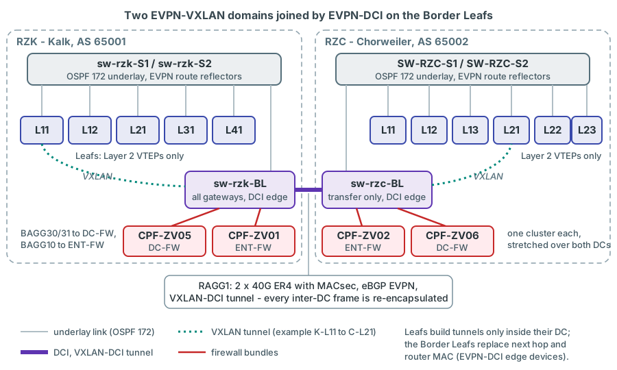
The Border Leafs are EVPN-DCI edge devices (EDs). Each BL keeps iBGP sessions to its own spines and runs an eBGP EVPN session, loopback to loopback, to each remote BL:
bgp 65001
 peer 172.31.0.252 as-number 65001
 peer 172.31.0.253 as-number 65001
 peer 172.31.1.254 as-number 65002
 peer 172.31.1.254 connect-interface LoopBack0
 peer 172.31.1.254 ebgp-max-hop 10
 peer 172.31.2.254 as-number 65003
 ...
 address-family l2vpn evpn
  peer 172.31.0.252 enable
  peer 172.31.0.252 next-hop-local
  peer 172.31.0.253 enable
  peer 172.31.0.253 next-hop-local
  peer 172.31.1.254 enable
  peer 172.31.1.254 router-mac-local
  peer 172.31.2.254 enable
  peer 172.31.2.254 router-mac-local
#
interface Route-Aggregation1
 description -> Channel to BL-Chorweiler
 ip address 172.31.0.1 255.255.255.252
 dci enable
verified from the running configuration; sw-rzc-BL is the mirror image (AS 65002,
next-hop-local towards 172.31.1.252/.253, router-mac-local towards 172.31.0.254). Both Border Leafs also carry
hardware-resource vxlan border.
The EVPN configuration guide describes exactly this model (EVPN Configuration Guide R630x, PDF pp. 115-117):
- A VXLAN tunnel connects a VTEP to its local ED; a VXLAN-DCI tunnel connects two EDs.
- When an ED advertises routes to a local VTEP or a remote ED, it replaces the next hop and the router MAC with its own
(
next-hop-localtowards the local spines,router-mac-localtowards the remote ED). - "Each ED de-encapsulates incoming VXLAN packets and re-encapsulates them based on the destination before forwarding."
dci enableon the Layer 3 interface towards the remote ED is required for VXLAN-DCI tunnels, and EDs must use theborderhardware resource mode.
The diagnostic files confirm the result. Counting the next hops in display evpn route mac:
| Device | Next hops of remote MAC entries |
|---|---|
sw-rzk-L11 |
RZK Leafs 172.31.0.242-.245 directly; everything else (RZC, RZD) via 172.31.0.254 = sw-rzk-BL (2 702 entries) |
SW-RZC-L21 |
RZC Leafs 172.31.1.241-.246 directly; everything from RZK/RZD via 172.31.1.254 = sw-rzc-BL (2 811 entries) |
sw-rzk-BL |
RZK Leafs directly; RZC via 172.31.1.254 (2 906 entries, Tunnel5); RZD via 172.31.2.254 |
The examined Leafs have no tunnel to any VTEP in the other data centre. All examined VTEPs also carry vxlan tunnel
mac-learning disable (VXLAN Command Reference, PDF p. 52): remote MAC addresses are learned only from BGP EVPN routes,
never from the data plane.
sw-rzk-BL and on sw-rzc-BL, and crosses RAGG1.What an inter-DC frame goes through
A Layer 2 frame from AP K-L11 to AP C-L21 is encapsulated three times: sw-rzk-L11 -> sw-rzk-BL (VXLAN tunnel),
sw-rzk-BL -> sw-rzc-BL (VXLAN-DCI tunnel over RAGG1), sw-rzc-BL -> SW-RZC-L21 (VXLAN tunnel). Its latency
therefore contains two ED de-/re-encapsulations plus the DCI fibre, and the frame passes one spine in each data
centre.
Why the EDs hide the remote data centre
With next-hop and router-MAC replacement each VTEP only needs tunnels to the VTEPs of its own DC plus one tunnel to its own ED. The two ASes stay independent (an RZC Leaf needs no tunnel to any RZK loopback), and the DCI is a single, controllable choke point with MACsec. The price is that all inter-DC traffic is funnelled through the two Border Leafs.
The DCI: Route-Aggregation1
interface HundredGigE1/2/1
port link-mode route
description Link-to-BL CHORW
bandwidth 40000000
macsec desire
mka enable
port link-aggregation group 1
#
interface HundredGigE2/2/1 (same, second IRF member)
verified (MKA key lines omitted). The facts that matter for measurements:
- Capacity: two members, one per IRF member, on the MACsec module JH957A in slot 2. The transceivers are
40G_BASE_ER4_QSFP_PLUS(HPE JL306A, "Transfer Distance(km): 40(SMF)",display transceiver interface), so RAGG1 is 2 x 40G, not 2 x 100G. - Distance: ER4 optics are 40 km-class optics. They suggest that the RZK-RZC fibre is longer than 10 km. The real distance is not documented confirm with LVR. Light needs about 5 µs per km of fibre, so every kilometre adds 5 µs to every inter-DC measurement - per direction.
- Shared with production: RAGG1 carries all inter-DC production traffic. Monitoring streams are negligible; lab tests across the DCI need change control (Chapter 24).
- Two members, two possible paths: LACP hashes each flow onto one member. If the two member fibres are routed differently, two inter-DC streams can show different baseline latencies. That is a property of the DCI, not an error.
- Earlier measurement attempts: an accounting policy
iperf-counting(UDP destination port 5001) is applied inbound on RAGG1 of both Border Leafs and on BAGG31 ofsw-rzk-BL, andsw-rzk-BLFGE1/4/26 is labelled "ALLEGRO-TEST" (shut down). The TRex platform replaces such ad-hoc tests with a permanent solution.
The access model: from a tagged frame to a VXLAN packet
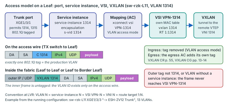
This is the most important section for TRex, because every TRex frame enters the fabric through it. LVR does not use
VLAN-based VXLAN mapping. Every server port is an 802.1Q trunk, and each VLAN on it is attached to a VSI through its own
Ethernet service instance. A real example from sw-rzk-L11:
interface Ten-GigabitEthernet1/3/3
port link-mode bridge
description -> ESH-ZV12 Trunk
port link-type trunk
undo port trunk permit vlan 1
port trunk permit vlan 147 176 252 1054 1080 to 1082 1280 1309 1380 1383 1397 to 1398
lldp compliance admin-status cdp txrx
#
service-instance 147
encapsulation s-vid 147
xconnect vsi VPN-147
#
service-instance 176
encapsulation s-vid 176
xconnect vsi VPN-176
... (one block per VLAN, 13 in total)
verified from the running configuration in the diagnostic file.
| Line | What it does | Why |
|---|---|---|
port link-type trunk |
The port accepts and sends 802.1Q-tagged frames | One server uses many VLANs |
undo port trunk permit vlan 1 / port trunk permit vlan ... |
Removes the default VLAN 1, permits exactly the VLANs in use | Hygiene: the permit list documents the service instances |
service-instance 147 |
Creates an Ethernet service instance (AC) on the port; the ID is local to the port (1-4096) | LVR uses the VLAN ID as instance ID for readability |
encapsulation s-vid 147 |
Frame match criterion: frames whose outer 802.1Q tag is 147 belong to this instance | Classification by tag (VXLAN Command Reference, PDF pp. 24-25) |
xconnect vsi VPN-147 |
Maps the instance to VSI VPN-147; no access-mode keyword means the default VLAN access mode |
The VSI forwards by its own MAC table (VXLAN Command Reference, PDF pp. 54-55) |
The VSI itself is defined once per switch and is identical on every VTEP:
vsi VPN-1314
description Tier 3 Services DataCenter
vxlan 1314
evpn encapsulation vxlan
route-distinguisher auto
vpn-target 1:1314 export-extcommunity
vpn-target 1:1314 import-extcommunity
verified (identical on SW-RZC-L21; on the Border Leafs the gateway VSIs carry one more
line, gateway vsi-interface 914). The naming convention is strict and useful: VLAN N on the port, service instance N,
VSI VPN-N, VXLAN ID (VNI) N, route target 1:N. The route distinguisher is generated automatically per VTEP.
What VLAN access mode does to the tag
The access mode decides what happens to the 802.1Q tag when a frame enters or leaves a VSI. In VLAN access mode (the default):
- "For an Ethernet frame received from the local site, the VTEP removes all its 802.1Q VLAN tags before forwarding the frame."
- "For an Ethernet frame destined for the local site, the VTEP adds 802.1Q VLAN tags to the frame before forwarding."
- "In VLAN access mode, VXLAN packets sent between sites do not contain 802.1Q VLAN tags."
(VXLAN Command Reference R630x, PDF p. 55; VXLAN Configuration Guide R630x, PDF pp. 13-14.) Inside the fabric the inner frame is untagged; the VLAN ID only exists on the access wire, and the egress port re-adds the tag of its own service instance.
Why this matters for TRex
The Leaf decides by the tag that is on the wire. A TRex frame must therefore arrive at the Leaf with exactly one 802.1Q tag whose VLAN ID is the production VLAN under test - no more, no less. That is the job of the TX switch: TRex sends two tags, the TX switch removes the outer one before the frame leaves towards the Leaf (Chapter 12). A frame that still carried the outer tag would match no service instance and would be dropped by the Leaf.
Two more details you will meet in the configurations:
- Access ports use the same model with a different match criterion:
port access vlan 229plusservice-instance 229/encapsulation untagged/xconnect vsi VPN-229(sw-rzk-L11XGE1/3/4, "ESH-ZV12 vMotion"). TRex APs always use the trunk variant. - VSI state:
display l2vpn vsionsw-rzk-L11lists 476 VSIs, "101 up, 375 down". VSIVPN-1314is Down onsw-rzk-L11andSW-RZC-L21(no local AC) and Up on both Border Leafs (they have an AC on BAGG31, see below). After you configure an AP, the VSI on that Leaf is expected to come up confirm on device.
Where routing happens: centralised gateways on sw-rzk-BL
The Leafs are pure Layer 2 VTEPs: neither sw-rzk-L11 nor SW-RZC-L21 has a single Vsi-interface with an IP address.
All switch gateways live on the Border Leafs, and in practice on one of them. This is the centralised EVPN
gateway model: one VTEP terminates the VXLANs and routes for everybody (EVPN Configuration Guide R630x, PDF pp. 10-11).
The VRFs (ip vpn-instance) on the Border Leafs:
| VRF | RD / route target | Purpose |
|---|---|---|
| VPN-CORE | 40:1 | Data-centre core: server gateways, transfers to both firewalls. Scope of TRex |
| VPN-WAN | 30:1 | WAN, transfer to the ENT-FW (later scope) |
| VPN-WLAN | 20:1 | WLAN client gateways, transfer to the ENT-FW (later scope) |
| MGMT | 10:1 | Out-of-band management (M-GigabitEthernet0/0/0) |
sw-rzk-BL has 19 VSIs with a gateway vsi-interface line:
| VRF | Vsi-interfaces on sw-rzk-BL | Notes |
|---|---|---|
| VPN-CORE, active | Vsi2 (VSI VPN-1002, 10.0.2.1/24), Vsi504 "WLAN-MGMT", Vsi914 / Vsi915 (VLAN 1314/1315) | |
| VPN-CORE, transfer | Vsi40 (VSI 4002, 10.9.0.17/29, to the ENT-FW), Vsi44 (VSI 4004, 10.9.0.33/29, to the DC-FW) | Vsi45 "to SZ-FW" exists without a VSI |
| VPN-CORE, shut down | Vsi109, 111, 112, 114, 115, 301, Vsi50 "Transfer RZD RZC RZK" | Gateways exist but are administratively down |
| VPN-WLAN | Vsi20 (VSI 4000, 10.9.0.1/29, transfer), Vsi507, 508, 511, 517 (WLAN clients, DHCP relay) | |
| VPN-WAN | Vsi30 (VSI 4001, 10.9.0.9/29, transfer) | |
| L3 VNIs | Vsi21 (l3-vni 64201, WLAN), Vsi31 (64301, WAN), Vsi41 (64401, CORE) |
Inter-BL routing via EVPN IP prefix routes |
sw-rzc-BL has only the transfer and L3-VNI interfaces (Vsi20, 21, 30, 31, 40, 41, 44, 50): no server-VLAN gateway at
all. Both Border Leafs also carry service-loopback group 1 type vsi-gateway with HGE1/1/8 and HGE2/1/8 ("Service-Loopback
100G") as members. HPE requires such a group when a 5950 4-slot acts as EVPN gateway (EVPN Configuration Guide R630x,
PDF p. 28): its member ports loop packets sent out by the device back into it, and the VSI-gateway type carries the VSI
gateway traffic (Layer 2 Configuration Guide R630x, PDF p. 375). Routed traffic on the Border Leafs therefore passes the
service loopback group, and this internal loop is part of the routing hop that every routed TRex stream measures. How much
latency it adds is not documented confirm on the bench.
The gateway MAC address is advertised to the Leafs by EVPN with the gateway flag. On sw-rzk-L11, VSI VPN-1314 contained
nothing else in February 2025:
VSI name: VPN-1314
MAC address Link ID/Name Flags Nexthop
ec9b-8b67-37b8 Tunnel4 BG 172.31.0.254
VSI name: VPN-1315
MAC address Link ID/Name Flags Nexthop
ec9b-8b67-37b8 Tunnel4 BG 172.31.0.254
verified real output. Flags B = learned from BGP EVPN, G = gateway entry (EVPN Command
Reference R630x, PDF pp. 23-24). ec9b-8b67-37b8 is the MAC address that a TRex client in VLAN 1314 receives when it
resolves its gateway 10.3.14.1 by ARP (Chapter 6).
Check during commissioning: the gateway MAC on the RZC Leafs
In the February 2025 files the gateway MAC ec9b-8b67-37b8 is present on sw-rzk-L11 and on sw-rzc-BL (flag BG,
via the VXLAN-DCI tunnel to 172.31.0.254), but it does not appear anywhere in the diagnostic file of SW-RZC-L21:
its display evpn route mac has no gateway (G) entries at all, and its display evpn route arp suppression is
empty. If an RZC Leaf does not know the gateway MAC, routed TRex frames from an RZC AP are unknown unicast for that
Leaf: they still reach the gateway via sw-rzc-BL, but they are also flooded to every other VTEP of the VSI - including
the other RZC APs, where TRex would count them as duplicates.
confirm on device After the first EMU clients are up, run
display evpn route mac vsi VPN-1314 (flag BG) or display l2vpn mac-address vsi VPN-1314 on an RZC Leaf and look for
ec9b-8b67-37b8. If it is missing, raise it with the fabric team before you trust RZC-sourced L3 results.
ARP towards the centralised gateway
The EVPN configuration guide attaches a condition to the centralised gateway model: "If an EVPN network contains a
centralized EVPN gateway, you must enable ARP or ND flood suppression on VTEPs. Typically remote ARP or ND learning is
disabled in an EVPN network. When ARP or ND requests for the gateway MAC address are sent to the centralized EVPN gateway
through VXLAN tunnels, the gateway does not respond to the requests." (EVPN Configuration Guide R630x, PDF p. 28.) That
is exactly the situation of an EMU client behind a Leaf AP: its ARP request for 10.3.14.1 reaches sw-rzk-BL through a
VXLAN tunnel.
LVR does not follow this guideline, and the configurations show why it may still work:
| Setting | HPE guidance | LVR, February 2025 |
|---|---|---|
ARP flood suppression, arp suppression enable (VSI view) |
Required on the VTEPs when a centralised gateway is used (PDF p. 28) | Not configured in any VSI - disabled, the default |
Remote ARP learning, vxlan tunnel arp-learning disable (system view) |
Disabling it is the best practice (PDF p. 36) | Not configured - remote ARP learning is enabled, the default |
Remote MAC learning, vxlan tunnel mac-learning disable (system view) |
Disabling it is the best practice (PDF p. 36) | Configured on every examined VTEP |
The guide ties the missing reply to remote ARP learning being disabled, and at LVR it is enabled. The diagnostic files
show remote ARP learning at work: the ARP table of sw-rzk-BL held 177 dynamic entries learned on Tunnel5, the VXLAN-DCI
tunnel to sw-rzc-BL - hosts in RZC exchange ARP with gateways on sw-rzk-BL through a VXLAN tunnel. It held no entry
learned on a tunnel to an RZK Leaf, so for the case that matters for TRex - a client behind a Leaf AP - there is no
evidence either way.
Check during commissioning: a client behind a Leaf AP must resolve its gateway
confirm on device When the first Leaf APs go live (rollout phase 3 of the plan, APs
K-L11 and C-L21), confirm that an EMU client behind a Leaf AP resolves 10.3.14.1: the client shows the gateway MAC
ec9b-8b67-37b8 (Chapter 6), and display arp vpn-instance VPN-CORE on sw-rzk-BL lists the
client address (10.3.14.101 for K-L11) on the tunnel towards that Leaf. If the gateway does not answer, two fallbacks
exist:
- ARP flood suppression in the Leaf VSIs:
arp suppression enablein VSI view (VXLAN Command Reference R630x, PDF pp. 5-6; disabled by default). The Leaf then answers ARP requests on behalf of the gateway, as the guide intends. This is a production change in every Leaf VSI concerned and needs the fabric team's approval; it also changes which ARP requests EMU still sees (Chapter 6). - Run the routed classes from the Border Leaf APs: at K-BL the client reaches Vsi914 on the same switch without any tunnel, and at C-BL its ARP request crosses the VXLAN-DCI tunnel on which the February 2025 data shows remote ARP learning at work. No fabric change is needed, but the Leaf part of the routed path is then not measured.
VPN-CORE and the two firewall clusters
Two Check Point clusters are attached to the Border Leafs. Both are stretched: one member per data centre.
DC firewall CPF-ZV05 / CPF-ZV06 ("DC-FW")
The DC-FW is the default gateway of most server VLANs - their gateway is a firewall VIP, not a switch. It is attached to each Border Leaf with two LACP bundles of 2 x 40G:
| Bundle (both BLs) | Description | Carries |
|---|---|---|
| BAGG30 (FGE1/3/25 + FGE2/3/25) | --> Channel to DC-FW inside |
VSI 4004 "Transfer VPN-CORE DC-FW", VSI 4005 "Transfer BL - Azubi-Test-FW" |
| BAGG31 (FGE1/3/26 + FGE2/3/26) | --> Channel to DC-FW Vlan-all |
trunk VLANs 32, 147-148, ..., 1000-1399, 4033 - about 450 service instances on sw-rzk-BL |
| BAGG32 | --> Channel DC-Firewall Sync |
VSI 196 "Sync DC-FW" |
The VPN-CORE side of the DC-FW is the transfer VSI 4004: Vsi44 is 10.9.0.33/29 on sw-rzk-BL and 10.9.0.34/29 on
sw-rzc-BL, the firewall VIP is 10.9.0.35. Both Border Leafs hold the same 35 static routes "zur DC-FW" in VPN-CORE,
for example:
ip route-static vpn-instance VPN-CORE 10.0.0.0 16 10.9.0.35 description zur DC-FW
ip route-static vpn-instance VPN-CORE 10.3.0.0 16 10.9.0.35 description zur DC-FW
ip route-static vpn-instance VPN-CORE 10.110.0.0 16 10.9.0.35 description zur DC-FW
verified (sw-rzc-BL has the same routes with preference 70).
Enterprise firewall CPF-ZV01 / CPF-ZV02 ("ENT-FW")
The ENT-FW is the hub between the VRFs. Each member is attached to its local Border Leaf with BAGG10 --> Channel to
ENT-FW ZV01 inside (on sw-rzc-BL: ... ZV02 inside), a trunk of VLANs 4000-4003:
| VSI | Description | Gateway on the BL |
|---|---|---|
| 4000 | Transfer VPN-WLAN | Vsi20 (VPN-WLAN) |
| 4001 | Transfer VPN-WAN ENT-FW | Vsi30 (VPN-WAN) |
| 4002 | Transfer VPN-CORE ENT-FW | Vsi40 (VPN-CORE, 10.9.0.16/29) |
| 4003 | Transfer ENTFW *frei* | none - free, no MAC addresses learned in February 2025; the TRex firewall zone in option B, the plan's default |
Further bundles: BAGG11 CPF-ZV01 - MAIN - DMZ (DMZ VLANs) and BAGG12 --> Channel CPF-ZV01- sync (VLAN 123
"Sync_FW-innen", untagged, VSI VPN-123).
The free VSI 4003 matters for TRex. vsi VPN-4003 (vxlan 4003, no gateway vsi-interface) exists on both Border
Leafs, each maps it with service-instance 4003 on its BAGG10 to the local firewall member, and display evpn
auto-discovery imet lists the other Border Leaf as its only remote VTEP: a stretched, empty segment that already reaches
both members. This makes it the TRex firewall zone of option B: the firewall team adds a VLAN 4003 interface (VIP
10.9.90.1) on the bond that already connects both cluster members to the Border Leafs, and TRex reaches the zone through
the Border Leaf attachment points K-BL and C-BL like any other VLAN (Chapter 13). The plan
recommends option B and uses it as the default; option A - a new firewall port per member on the TX switches, the
customer's original wish - remains the alternative decision
(Chapter 15).
VPN-CORE talks to the ENT-FW with OSPF: ospf 1 router-id 10.9.0.17 vpn-instance VPN-CORE with import-route direct and
import-route static. The ENT-FW appears with the same router ID in three OSPF processes - one per VRF:
OSPF Process 1 with Router ID 10.9.0.17
Router ID Address Pri Dead-Time State Interface
10.9.0.18 10.9.0.18 1 38 Full/DROther Vsi40
10.9.0.19 10.9.0.19 1 40 Full/DROther Vsi40
10.9.0.22 10.9.0.22 1 38 Full/BDR Vsi40
OSPF Process 25 with Router ID 10.25.0.1
10.25.0.2 10.9.0.10 1 38 Full/DR Vsi30
10.9.0.22 10.9.0.14 1 38 Full/DROther Vsi30
OSPF Process 180 with Router ID 10.180.4.9
10.9.0.2 10.9.0.2 1 38 Full/DROther Vsi20
10.9.0.22 10.9.0.6 1 38 Full/BDR Vsi20
verified real output (headers shortened). 10.9.0.18 is sw-rzc-BL, 10.9.0.19 is sw-rzd-BL;
router ID 10.9.0.22 is the ENT-FW in VPN-CORE (OSPF 1), VPN-WAN (OSPF 25) and VPN-WLAN (OSPF 180).
The VPN-CORE routing table
Destination/Mask Proto Pre Cost NextHop Interface
0.0.0.0/0 O_ASE1 150 2 10.9.0.22 Vsi40
10.0.0.0/16 Static 60 0 10.9.0.35 Vsi44
10.3.0.0/16 Static 60 0 10.9.0.35 Vsi44
10.3.14.0/24 Direct 0 0 10.3.14.1 Vsi914
10.3.15.0/24 Direct 0 0 10.3.15.1 Vsi915
10.9.0.16/29 Direct 0 0 10.9.0.17 Vsi40
10.9.0.32/29 Direct 0 0 10.9.0.33 Vsi44
verified real output. Read it as three rules:
- Subnets with a gateway on
sw-rzk-BLare directly connected (10.3.14.0/24, 10.3.15.0/24). They lie inside the static aggregate 10.3.0.0/16 to the DC-FW, but the longer prefix wins. - Server subnets behind the DC-FW are reached by static routes via 10.9.0.35 (Vsi44).
- Everything else follows the default route to the ENT-FW (0.0.0.0/0, OSPF external type 1, via 10.9.0.22 on Vsi40). A new subnet behind the ENT-FW - such as a TRex firewall zone - is therefore already routed to the ENT-FW from VPN-CORE without any switch change (an explicit OSPF advertisement by the firewall is still the cleaner design, Chapter 15).
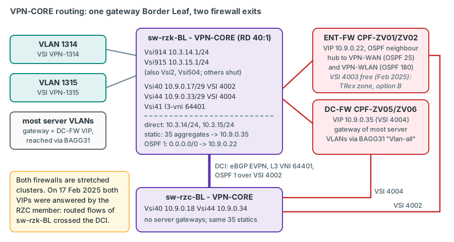
sw-rzk-BL; everything
routed leaves either to the DC-FW (static routes) or to the ENT-FW (default route) - and both are stretched clusters.One stretched cluster each - and where the active member was
Several observations show that CPF-ZV01/ZV02 form one ClusterXL stretched over both DCs rather than two clusters:
- both Border Leafs see a single OSPF neighbour 10.9.0.22 on Vsi40;
- in VSI 4002 the Check Point MAC
001c-7f65-8ec8is local onsw-rzk-BL(BAGG10, ZV01) and001c-7f65-ff14is local onsw-rzc-BL(ZV02); - the sync VLAN 123 "Sync_FW-innen" is a stretched VSI attached to BAGG12 on both Border Leafs.
The same pattern exists for the DC-FW (sync VSI 196 on BAGG32 of both Border Leafs). confirm with the firewall team
The ARP table of sw-rzk-BL even shows which member was active on 17 February 2025:
IP address MAC address VLAN/VSI Interface Aging Type
10.9.0.20 001c-7f65-8ec8 513 BAGG10 167 D
10.9.0.36 248a-0791-0234 515 BAGG30 356 D
10.9.0.21 001c-7f65-ff14 513 Tunnel5 -- R
10.9.0.22 001c-7f65-ff14 513 Tunnel5 -- R
10.9.0.35 506b-4b24-7280 515 Tunnel5 -- R
10.9.0.37 506b-4b24-7280 515 Tunnel5 -- R
verified real output (513 = VSI 4002, 515 = VSI 4004, Tunnel5 = VXLAN-DCI tunnel to
sw-rzc-BL). The ENT-FW VIP 10.9.0.22 resolves to the MAC of the RZC member (the same MAC as 10.9.0.21, learned through
the DCI), and the DC-FW VIP 10.9.0.35 resolves to a MAC that sw-rzc-BL learns locally on its BAGG30. In a ClusterXL
high-availability cluster the active member answers for the VIP, so on that day both active members were in
Chorweiler confirm the ClusterXL mode with the firewall team. Every VPN-CORE flow that
sw-rzk-BL routed to either firewall crossed the DCI to RZC and came back.
Note also which MAC answered: each VIP resolved to the MAC of the member's own address (10.9.0.21 and 10.9.0.37) - no
ClusterXL virtual MAC appeared in the tables confirm with the firewall team. That matters
for every TRex stream whose destination MAC is a firewall MAC, such as the L3-DCFW streams (their gateway is the DC-FW VIP)
and the zone-side clients of L3-ENTFW. The destination MAC is written into the packet when the stream is built, so after a
failover such a stream keeps sending to the former active member and loses packets until it is rebuilt with the newly
resolved MAC. EMU re-resolves the gateway periodically (by default every 60 s); the planned orchestrator trexctl gets a
gateway-MAC tracker that watches the resolved gateway MACs and rebuilds the affected streams, and until it exists you
remove and re-add them with the TRex console or Python API (Chapter 18). A ClusterXL virtual MAC
would avoid the issue. Test the behaviour during a planned failover (Chapter 15).
VLANs 1314 and 1315 in detail
The two "Performance-Test" VLANs are the primary carriers of the permanent monitoring. They exist on every examined switch:
| Attribute | VLAN 1314 | VLAN 1315 |
|---|---|---|
| VLAN description (all four switches) | t3_1314_webserv_win |
t3_1315_winserv |
| VSI / VNI / route target | VPN-1314 / 1314 / 1:1314, "Tier 3 Services DataCenter" |
VPN-1315 / 1315 / 1:1315, same description |
| Gateway | Vsi914 "Performance-Test VLAN 1314", 10.3.14.1/24, VPN-CORE - only on sw-rzk-BL |
Vsi915 "Performance-Test VLAN 1315", 10.3.15.1/24, VPN-CORE - only on sw-rzk-BL |
| DHCP | dhcp select relay, servers 10.10.252.252 and 10.10.254.254 |
same |
| STP | disabled for the VLAN on sw-rzk-L11 (1082-1399), SW-RZC-L21 (1087-1399), both BLs (1242-1329) |
same |
| Leaf ports (L11, RZC-L21) | none - VSI Down | none - VSI Down |
| Border Leaf ports | service instance on BAGG31 "Vlan-all" of both BLs | same |
| State February 2025 | no MAC learned except the gateway; the BL ARP table only had the gateway itself | same |
Three points need attention:
- The DC-FW is in the broadcast domain. BAGG31 permits 1000-1399 and carries service instances 1314 and 1315 on both
Border Leafs. Every broadcast and every unknown-unicast frame in these VLANs - TRex ARP requests and gratuitous ARPs
included - is delivered to the DC firewall, through both data centres. ARP flood suppression is not enabled anywhere
(
arp suppression enableappears in no configuration; it is disabled by default, EVPN Configuration Guide R630x, PDF p. 42), so every ARP request is flooded through the whole VSI (see also ARP towards the centralised gateway). - Conflicting names. The VLAN descriptions say "webserv_win"/"winserv" while the gateways say "Performance-Test". confirm with LVR that 1314/1315 are reserved for tests and that the DC-FW has no interface or IP address in them.
- DHCP relay is active. The DHCP scopes for 10.3.14.0/24 and 10.3.15.0/24 must exclude the TRex pools (10.3.14.101-116, 10.3.15.101-116) and, for the lab tests that preferably run in these VLANs, the lab-client range .151-.166, which needs its own IPAM reservation confirm with LVR.
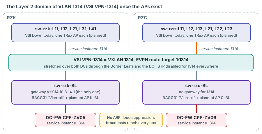
sw-rzk-BL and - through BAGG31 on both Border Leafs - the DC firewall.Why use these VLANs at all? They exist on every VTEP examined, they are unused, they have a switch gateway in VPN-CORE (needed for the class L3-BL, Chapter 14), and they reach the ENT-FW through the VPN-CORE default route (class L3-ENTFW). STP is already disabled for them, so a new AP forwards immediately after link-up.
STP in the fabric
All examined Leafs and Border Leafs carry stp mode pvst in their configuration (the spine configurations contain no STP
settings), and STP is switched off for long lists of VLANs, for example on sw-rzk-L11:
undo stp vlan 162 171 181 206 341 362 405 508 1082 to 1399 enable
stp mode pvst
These lines are inactive, however: the configurations contain no stp global enable, and display stp on all four
examined switches (sw-rzk-BL, sw-rzc-BL, sw-rzk-L11, SW-RZC-L21) reports "Protocol status: Disabled" - spanning
tree is globally off verified. None of the examined RZK or RZC switches uses
stp edged-port or BPDU protection on any port (only the out-of-scope sw-rzd-BL has stp port bpdu-protection enable
on its links to other sites). So on these switches a new AP forwards immediately after link-up in every VLAN, they send
no BPDUs of their own, and nothing would block a Layer 2 loop: the fabric relies on correct cabling and on the TX switch
never bridging two APs (Chapter 12). For the Leafs without diag files, display stp brief before
the rollout shows whether they behave the same confirm on device
(Chapter 13).
What this means for measurements
| Fact about the fabric | Consequence for TRex results | Details |
|---|---|---|
Gateways only on sw-rzk-BL |
A routed stream between two RZC APs crosses the DCI twice (to Kalk and back), between an RZC and an RZK AP once; RZK- and RZC-sourced L3 streams have different baselines | Ch. 14 |
| Inter-DC traffic is re-encapsulated on both EDs | Inter-DC latency includes two ED passes, the DCI fibre (~5 µs/km) and one spine per DC | Ch. 14 |
| The gateway BL uses a VSI-gateway service loopback group | Routed streams (L3-BL, L3-ENTFW) include an internal loop through the service-loopback ports of sw-rzk-BL |
this chapter |
| Centralised gateway without ARP flood suppression | Whether a client behind a Leaf AP resolves 10.3.14.1 must be confirmed during commissioning; fallbacks are ARP flood suppression or the BL APs | this chapter |
| Firewalls are stretched clusters, active member possibly in RZC, member MACs | Firewall classes may cross the DCI; a failover moves the path and causes a latency step, and streams addressed to the former member's MAC lose packets until they are rebuilt | Ch. 15 |
| RAGG1 = 2 x 40G with MACsec, shared with production | Lab tests across the DCI need change control; per-member path differences are possible | Ch. 24 |
| 1314/1315 reach the DC-FW via BAGG31; no ARP suppression | TRex broadcasts and unknown unicast reach the DC firewall; line-rate lab tests in these VLANs are not isolated | Ch. 24 |
| Remote MACs only via BGP EVPN | A TRex client that stops sending ages out (300 s default) and its traffic becomes unknown unicast | Ch. 13 |
| No QoS trust or scheduling in the fabric (only the accounting policy) | DSCP classes are expected to behave the same; differences point to remarking or queuing, for example on a firewall | Ch. 14 |
Read latency per path, not per number
Before you call a latency value "high", write down its path: which DC, which Leafs, DCI yes/no, routed on sw-rzk-BL
yes/no, firewall yes/no and which member is active. Most "anomalies" during commissioning will turn out to be path
differences that this chapter predicts.
Verifying the picture yourself
Everything above can be checked read-only. Commands marked "diag" were run in the February 2025 diagnostic files; the others are documented for the 5950 R630x.
| What you want to know | Command (where) | What to look for | Source |
|---|---|---|---|
| Release, modules | display version, display device manuinfo (any) |
Release line; JH180A in the slot of the AP | diag; Fundamentals CR p. 273 |
| Underlay neighbours | display ospf peer (any) |
Spines Full; on the BLs also RAGG1 | diag; L3 IP Routing CR p. 181 |
| EVPN MAC entries | display evpn route mac vsi VPN-1314 (Leaf, BL) |
Local entries "DL", remote "B" with next hop; gateway "BG" | diag; EVPN CR p. 23 |
| VSI state, ACs, tunnels | display l2vpn vsi name VPN-1314 verbose (Leaf, BL) |
State Up, the AP's AC listed | diag (brief form); VXLAN CR pp. 17-19 |
| MAC table of a VSI | display l2vpn mac-address vsi VPN-1314 (Leaf, BL) |
Local TRex MACs on the AP port, remote ones on tunnels | VXLAN CR p. 13 |
| Service instances of a port | display l2vpn service-instance interface Ten-GigabitEthernet1/3/3 verbose |
Encapsulation, VSI name, state | VXLAN CR pp. 15-16 |
| VPN-CORE routes | display ip routing-table vpn-instance VPN-CORE 10.3.14.0 24 (BL) |
Direct on Vsi914 | diag (all-vpn-instance); L3 IP Routing CR pp. 25-26 |
| Firewall next hops | display arp vpn-instance VPN-CORE (BL) |
10.9.0.22 / 10.9.0.35 and the interface they are learned on | diag (display arp all); L3 IP Services CR p. 33 |
| Gateway ARP for TRex clients | display arp vpn-instance VPN-CORE (sw-rzk-BL) |
The TRex client addresses (for example 10.3.14.101) on the tunnel towards the AP's Leaf | L3 IP Services CR p. 33 |
| DCI members and optics | display link-aggregation verbose, display transceiver interface (BL) |
Both members selected; 40G ER4 | diag; L2 CR p. 127, Fundamentals CR p. 291 |
Long outputs can be filtered with | include; the regular expression may contain | for "or" (Fundamentals
Configuration Guide R630x, PDF pp. 21-22). For example, to find which member owns the firewall VIPs today:
confirm on device (the filter syntax is documented; the regular expression is an
example). If the VIP shows the same interface as the RZC member's address (a tunnel towards sw-rzc-BL when you run it on
sw-rzk-BL), the active member is in Chorweiler.
Key takeaways
- The fabric is two EVPN-VXLAN domains (AS 65001 RZK, AS 65002 RZC) with spines as route reflectors and the Border Leafs as EVPN-DCI edge devices; an inter-DC frame is encapsulated three times and crosses RAGG1 (2 x 40G ER4, MACsec) once.
- The OSPF 172 underlay is one area across both DCs; remote MACs are learned only from BGP EVPN
(
vxlan tunnel mac-learning disable). - Every access port is a trunk with one Ethernet service instance per VLAN (
encapsulation s-vid N,xconnect vsi VPN-N); in the default VLAN access mode the tag is removed on entry and re-added on exit. - A TRex frame must reach the Leaf with exactly one tag - the production VLAN. The TX switch guarantees that.
- All switch gateways are centralised on
sw-rzk-BL(VPN-CORE, VPN-WAN, VPN-WLAN);sw-rzc-BLonly has transfer interfaces. RZC-sourced routed traffic always travels to Kalk. - VPN-CORE reaches the DC-FW by static routes (10.9.0.35, Vsi44) and everything else by the OSPF default route to the ENT-FW (10.9.0.22, Vsi40). Both firewalls are stretched clusters; in February 2025 both active members were in RZC and answered with member MACs - streams towards a firewall MAC must be rebuilt after a failover unless a virtual MAC is used.
- The free transfer VSI 4003, already on BAGG10 to both ENT-FW members, is the plan's default for the TRex firewall zone (option B, reached through the Border Leaf APs); a new firewall port per member on the TX switches (option A) is the alternative.
- The centralised gateway runs without ARP flood suppression, against HPE's guideline. Remote ARP learning is enabled, but
whether a client behind a Leaf AP resolves 10.3.14.1 must be confirmed during commissioning; the fallbacks are
arp suppression enablein the Leaf VSIs or routed classes from the BL APs. - VLANs 1314/1315 are unused "Performance-Test" VLANs with a gateway on
sw-rzk-BL, but they are also mapped to the DC-FW on BAGG31 of both Border Leafs. - Treat the February 2025 data as a snapshot and verify it with the read-only commands before each change.
Check your understanding
1. A TRex frame enters sw-rzk-L11 on an AP with the tag 1314. What exactly happens to the tag, and what does the VXLAN packet towards sw-rzk-BL contain?
The tag selects service instance 1314 (encapsulation s-vid 1314), which maps the frame into VSI VPN-1314. Because
the instance uses the default VLAN access mode, the VTEP removes the 802.1Q tag before forwarding. The VXLAN packet
carries VNI 1314 in its VXLAN header and an untagged inner Ethernet frame. The egress port adds the tag of its own
service instance again.
2. Why does a routed stream between two RZC APs (VLAN 1314 to VLAN 1315) cross the DCI twice per direction?
The only gateways for 1314 and 1315 are Vsi914/Vsi915 on sw-rzk-BL; sw-rzc-BL has no server-VLAN gateways. The
frame must travel in VSI 1314 from RZC to Kalk (first DCI crossing), is routed there into VSI 1315, and travels back to
RZC (second crossing). A routed stream between an RZC and an RZK AP crosses the DCI once, an RZK-to-RZK routed
stream zero times.
3. Which evidence suggests that CPF-ZV01/ZV02 are one stretched cluster, and why does that matter for TRex?
Both Border Leafs see one OSPF neighbour 10.9.0.22; each Border Leaf has one Check Point MAC locally in VSI 4002; the
sync VLAN 123 is a stretched VSI. For TRex it means the firewall path depends on which member is active: if it is the
RZC member, flows routed by sw-rzk-BL cross the DCI to the firewall and back, and a failover changes the path and
shows up as a latency step. Because the members answered with their own MACs, streams addressed to the former active
member also lose packets after a failover until they are rebuilt with the new MAC.
4. You see the RZC MAC addresses on sw-rzk-L11 with next hop 172.31.0.254. Is that an error?
No. sw-rzk-BL is an EVPN-DCI edge device and replaces the next hop of routes it re-advertises to its spines
(next-hop-local). RZK Leafs therefore tunnel all inter-DC traffic to sw-rzk-BL, which de-encapsulates and
re-encapsulates it into the VXLAN-DCI tunnel to 172.31.1.254.
5. Why is VLAN 1314 not fully isolated even though no Leaf port carries it today?
Both Border Leafs map 1314 (and 1315) to BAGG31 "Channel to DC-FW Vlan-all", which permits VLANs 1000-1399. Broadcasts
and unknown unicast in VSI VPN-1314 therefore reach the DC firewall in both DCs. ARP flood suppression is not
enabled, so every TRex ARP request is flooded there as well. LVR must confirm that the DC-FW has no interface in the
VLAN, and line-rate lab tests in it need care.
6. What would you expect to see in the VPN-CORE routing table of sw-rzk-BL for a new subnet 10.9.90.0/24 behind the ENT-FW, before anybody configures anything?
No specific entry - but the default route 0.0.0.0/0 (O_ASE1 via 10.9.0.22, Vsi40) already covers it, so traffic from VPN-CORE is forwarded to the ENT-FW. Once the firewall advertises the subnet into OSPF 1 (or a static route is added), an explicit /24 entry appears.
7. A colleague wants to put an AP on sw-rzk-L11 port XGE1/2/5. What do you tell them?
Slot 2 of sw-rzk-L11 is a JH182A 10GBASE-T module (copper). The AP design uses 10G SFP+ fibre, so the port must be on
the JH180A SFP+ module in slot 3 - the free port found in February 2025 is XGE1/3/1.
8. After commissioning, all streams from RZC APs to the gateway 10.3.14.1 show more RX than TX packets. Where do you look first?
At the MAC table of VSI VPN-1314 on the RZC Leafs (display l2vpn mac-address vsi VPN-1314). If the gateway MAC
ec9b-8b67-37b8 is missing there, the Leaf floods the routed frames as unknown unicast to every VTEP of the VSI, and
the copies arriving at other RZC APs are counted by TRex as additional received packets.
References
- Diagnostic files (17/18 Feb 2025, project folder):
diag_sw-rzk-L11_20250217-164257.txt,diag_sw-rzk-BL_20250217-163816.txt,diag_SW-RZC-L21_20250218-075107.txt,diag_sw-rzc-BL_20250217-163904.txt,diag_sw-rzk-S1_20250217-164112.txt,diag_SW-RZC-S1_20250217-164016.txt- commandsdisplay current-configuration,display device manuinfo,display interface brief,display ospf peer,display evpn route mac,display evpn route arp suppression,display evpn auto-discovery imet,display l2vpn vsi,display arp all,display ip routing-table all-vpn-instance,display transceiver interface. - "Big Picture-Rechenzentren-RZKC.pdf", page 1 (device inventory, loopbacks, firewall names).
- "LVR-InfoKom - Comware Switch Analysis v1.0.xlsx" (end-of-support dates, upgrade recommendation for
SW-RZC-L21). - HPE FlexFabric 5950 EVPN Configuration Guide R630x: PDF p. 6 (spines as RRs), PDF p. 8 (MAC learning), PDF pp. 10-11
(centralised EVPN gateway), PDF p. 28 (centralised gateway: ARP or ND flood suppression required on the VTEPs, service
loopback group), PDF p. 36 (remote MAC and ARP learning: defaults and best practice), PDF p. 42 (ARP flood suppression,
disabled by default), PDF pp. 115-117 (EVPN-DCI,
dci enable, next-hop and router-MAC replacement). - HPE FlexFabric 5950 EVPN Command Reference R630x: PDF pp. 23-24 (
display evpn route mac, flags). - HPE FlexFabric 5950 VXLAN Command Reference R630x: PDF pp. 5-6 (
arp suppression enable), PDF p. 13 (display l2vpn mac-address), PDF pp. 15-19 (display l2vpn service-instance,display l2vpn vsi), PDF pp. 24-25 (encapsulation), PDF pp. 54-55 (xconnect vsi, access modes), PDF p. 52 (vxlan tunnel mac-learning disable). - HPE FlexFabric 5950 VXLAN Configuration Guide R630x: PDF pp. 13-14 (access modes of VSIs).
- HPE FlexFabric 5950 Layer 2 - LAN Switching Configuration Guide R630x: PDF p. 375 (service loopback groups).
- HPE FlexFabric 5950 Layer 2 - LAN Switching Command Reference R630x: PDF p. 127 (
display link-aggregation verbose). - HPE FlexFabric 5950 Layer 3 - IP Routing Command Reference R630x: PDF p. 181 (
display ospf peer), PDF pp. 25-26 (display ip routing-table ... ip-address). - HPE FlexFabric 5950 Layer 3 - IP Services Command Reference R630x: PDF p. 33 (
display arp vpn-instance). - HPE FlexFabric 5950 Fundamentals Configuration Guide R630x: PDF pp. 21-22 (filtering display output, regular expressions).
- HPE FlexFabric 5950 Fundamentals Command Reference R630x: PDF p. 273 (
display device manuinfo), PDF p. 291 (display transceiver interface).